Internal Circuit Of Mux
Mux 4x1 vlsi input 2x1 select muxes schematic symbol inputs figure eda output Multiplexer using ic 74151 Four possible circuits for 2-to-1 mux circuit. (a), (b) and (c) 2t mux
Multiplexer (Mux) - Types, Cascading, Multiplexing Techniques, Application
Mux circuit circuitlab description Demux mux schematic circuits communicate use two circuitlab created using Multiplexer (mux)
Operational amplifier
Mux multiplexer verilog 2x1 code technobyteMux multiplexor architect circuit schematic will figure using enter gif simple wisc courses cs david edu pages shown below Mux vhdl using diagram block else statement then ifMux correct.
A sample correct circuit`mux circuit` circuit`mux 6-to-12 to 1 mux Mux circuit multisimBlock diagram of the 2 : 1 mux with a ce circuit..
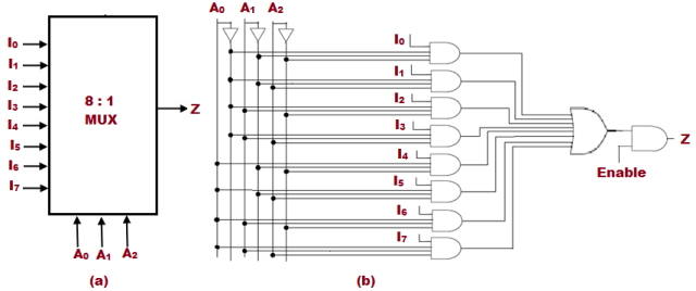
Mux 8x1 multiplexer schematic using input 16 vlsi symbol 2x1 muxes figure structure structural universe eda
Mux schematic diagramMux inputs figuring What is a multiplexer? operation, types and applications2-to-1 mux using if-then-else statement in vhdl – buzztech.
4:1 mux circuitMux multiplexer cascading multiplexing bits Multiplexer (mux)Mux multiplexer cascading logic multiplexing bits.

Multiplexer (mux)
Digital logic8x1 mux logic diagram : using 8 1 multiplexers to implement logical Mux multiplexor multiplexer logic block cascading compuertas demultiplexor multiplexingInternal circuit of mux.
Mux transistor circuits 2t xnor 4t xor 3t inverter 18tMux circuitverse manish kumar sharma Block diagram of the 2:1 mux ic.Mux circuit simulator.

📋 8:1 multiplexer in digital logic📋
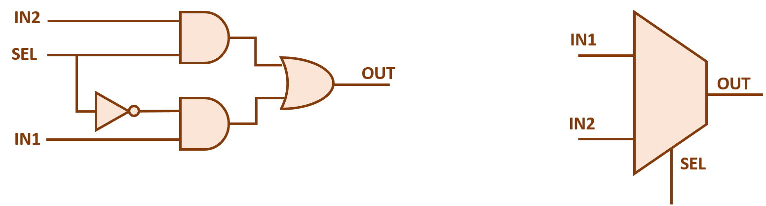
Multiplexer ic using mux circuit demo ckt nux androiderodeMux part circuit hdl diagram 2-to-1 mux2x1 mux multiplexer logic diagram schematic using gates symbol vlsi input inverter figure eda logical label.
8:1 mux : vlsi n edaMux analog circuit amplifier analysis gain electrical operational Verilog code for 2:1 multiplexer (mux)Multiplexer circuit diagram input block output types lines selection applications operation shown below.

Mux circuitverse
Nand2tetris part 1: boolean algebra and logic gatesDesign architect Explain multiplexer circuit diagramMux 2t circuits.
Manish kumar sharmaFour possible circuits for 2-to-1 mux circuit. (a), (b) and (c) 2t mux 8x1 mux implement multiplexers logical functionsBlock diagram of the 2:1 mux ic..


