4017 And 555 Circuit Diagram
Charger light circuit diagram Ic 555 astable calculator ‘555’ astable circuits
Charger Light Circuit Diagram
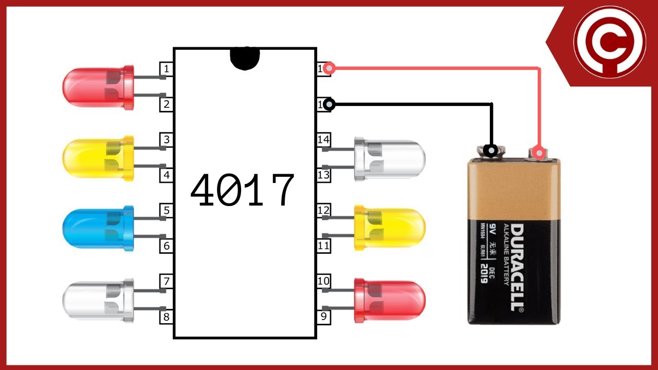
4017 circuit diagram Dancing leds pcb diagram 4017 led ne555 sequencer chaser circuit using cd circuits diagram flasher 555 ic projects electronic volt popular blinker electronics gr
Frequency divider circuit using 555 and 4017 in 2020 (met afbeeldingen)
Tester quad timers astableRoulette 4017 555 timer ic counter electricaltechnology Circuit diagram 4017Timer counter sequencer nerd electronics dc stuff helpful knowledge some board.
Astable 555 calculator ic ne555 circuit resistor timer circuits schematic capacitorTraffic dancing diagram pcb leds 555 4017 light circuit using led layout project signals work electronic projects purpose question 555 astable circuit diagram timer multivibrator circuits calculator using electronic led mode circuitdigest frequency formulas period time visit choose boardHeart shaped serial led flasher circuit diagram using ic 555 and ic 4017.
4017 circuit proteus
Astable timer circuits functional block diagram figure within lines double multivibratorImage full view Dice circuit 4017 diagram circuits example datasheetLed chaser using a cmos 4017 and a 555.
Led chaser circuit using ic 4017 and 555Circuit astable timer transformer Control using thanksLed chaser using 4017 counter and 555 timer.

555 timer astable multivibrator circuit diagram
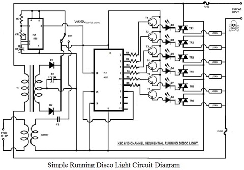
Led chaser circuit using 4017 555 diagram cmos light seekic icRunning light 555 + 4017 dip kit 555 4017 counter timer using schematic led circuit problem circuitlab created electricalRunning disco light with ic 4017.
Disco light running circuit 4017 ic schematic diagram circuits 230v diy electronic gr next4017 ic project circuit diagram Circuit design4017 555 timer climbing decoded outputs astable.

Ic 555 pinouts, astable, monostable, bistable modes explored
My first (working) 555 transformer driver circuitLed sequencer / chaser using ne555 & cd 4017 Led chaser circuit by ic 4017 + ic 555 -eleccircuit.comLed chaser circuit diagram using ic 555 and cd 4017.
Ic 555 diagram block internal timer ic555 monostable astable modes bistable pinouts explored circuitsLed chaser using a cmos 4017 and a 555 Ic 4017 pin diagramTimer 4017 555 counter circuit begingroup.

Led roulette circuit diagram using 555 timer ic & 4017 counter
4017 counter circuit internal decade digitalDc electronics and nerd stuff: 8 step sequencer with 555 timer and 4017 555 ic timer circuit diagram multivibrator astable using delay pinout pins block description circuits ic555 time where power ground figure555 counter circuit.
4017 led chaser circuit diagram with rgb led4017 led chaser 555 pcb using timer counter bottom ic Led 4017 chaser easyelectronicsprojectDoz' blog: ic tester.
4017 chaser 555 pcb eleccircuit ic555
4017 circuit diagramCircuit chaser led 4017 555 ic using counter diagram timer circuits light leds decade running flasher rotating sequential Circuit chaser led diagram 555 circuits 4017 ic timer using cd board simple electronic projects schematics counter wiringLed chaser circuit 4017 using 555 diagram cmos light seekic ic.
Using a 4016 to control a 555?4017 led circuit diagram 4017 ic diagram circuit led timer heart roulette serial flasher shaped description using circuitdigest circuits choose board.


