3 Phase Pwm Inverter Circuit Diagram
Phase motor single circuit three inverter supply diagram driving driver ac generator circuits homemade using make connection bridge electronic battery Three-phase voltage source pwm inverter the circuit model of a typical Three phase inverter circuit
Three phase inverters
Figure 1 from the use of harmonic distortion to increase the output 3 phase power circuit diagram Week-6 challenge: ev drivetrain : skill-lync
3 phase pwm inverter
Inverter arduinoPwm inverter phase figure three voltage harmonic distortion increase use output Phase inverter circuit homemade diagram circuits board driver ic three arduino using bridge single wiring electronic generator projects electronics choose3 phase power circuit diagram.
Terupdate 24+ inverter motor ac 3 phaseInterlocking gate drivers for improving the robustness of three-phase 3-phase pwm power inverter circuitPwm idh.

Three phase inverter circuit
Inverter circuit pwm tl494 ic sine wave modified using pinout circuits application makingcircuits simplest ne555 inspirasi functions discuss versatile basedInverter pwm circuit phase power system three rectifier Pwm invertersThree phase inverter: it's basics and circuit diagram.
3 phase pwm inverterInverter phase 12 3 phase inverter circuit diagram robhosking diagram3 phase pwm inverter uses how many pulses?.

3 phase pwm power inverter circuit
Arduino three phase inverter codePhase three gate inverter isolated inverters drivers industrial vfd robustness ti interlocking improving schematic 3phase figure Inverter drivetrainCircuit inverter phase boost invertor circuits trifazic schema buck transformer inversor converter wiring 220v scheme electrice baterie 60v diagrama wave.
Simple 3 phase inverter circuitPwm inverter e2e Three phase inverter circuitInverter pwm.
Simple 3 phase inverter circuit
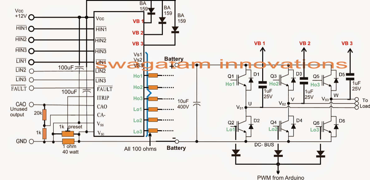
Phase inverter circuit three homemade dc wiring diagram circuits control power generator schematic signal projects code color arduino make wireMake this 3 phase inverter circuit Simple 3 phase inverter circuitSimplest pwm modified sine wave inverter circuit using ic tl494.
Pin on circuit diagramSo, which pwm technique is best (part 6) Inverter pwmInverter pwm modulation.

Phase circuit inverter three generator circuits homemade simple incorporate stages regarding processor basic discussion following learn let these first
12+ 3 phase inverter circuit diagramArduino inverter phase circuit pwm using make code driver diagram ic bridge projects circuits chip sinewave homemade forms above second Phase circuit inverter three generator signal converters pwm diagram shifted1, three phase inverter circuit.
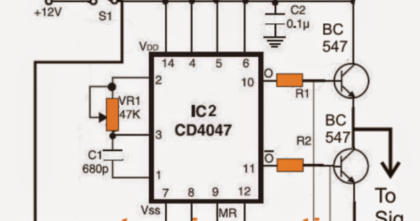
Three-phase inverter circuitInverter phase pwm circuit six diagram Three phase inverter circuit inverters open switchesPhase inverter circuit circuits generator three homemade simple diagram wave push pull single arduino 4047 motor power driver control using.

3 phase pwm inverter circuit for idh
Inverter pwmThree-phase pwm inverters with a r-l load. Make this 3 phase inverter circuit ~ electronic circuit projectsCircuit inverter phase diagram three.
Interfacing arduino pwm with any inverter circuitThree phase inverter circuit diagram – diy electronics projects Three phase invertersHow a 3 phase pulse width modulation (pwm) vfd inverter works.


