3 Bit Binary Adder Circuit Diagram
Adder logic binary circuit gates diagram using array inputs made twice labeled below used also Binary adder and subtraction circuits along with its various types Adder circuitlab
What is Parallel Binary Adder? - 2-Bit and 5-Bit Parallel Binary Adder
Square 3 bit input using two 3 bit adders and logic gates Adder bit logic diagram combination tutor boolean gif public tutorial circuits Adder parallel circuitverse binary
Adder bit circuit digital logic gate gates interview adders division questions using addition electronics diagram delay transistors xor logisim carry
A binary adder made using and-or array logicElectronic – how to make 2 bit or more half adder circuit – valuable 4 bit adder circuit diagramMultisim adder bit.
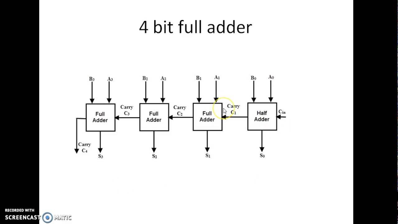
Adder bit circuit logic carry a1 a2 stackexchange b2 b1 xorAdder subtractor binary circuitverse Binary adder subtractor bit subtraction addition operation which value either😊 four bit parallel adder. 4 bit binary adder circuit / block diagram.

Adder bit circuitverse
4 bit parallel adder circuit diagramAdder parallel binary serial bits gif stack first results What is parallel binary adder?Binary adder circuit / circuit additionneur binaire.
3 bit adder logic circuit design4 bit binary adder circuit diagram Proposed 1-bit full adder circuit.Használható melbourne tömör 4 bit subtractor truth table zenei ban ben.

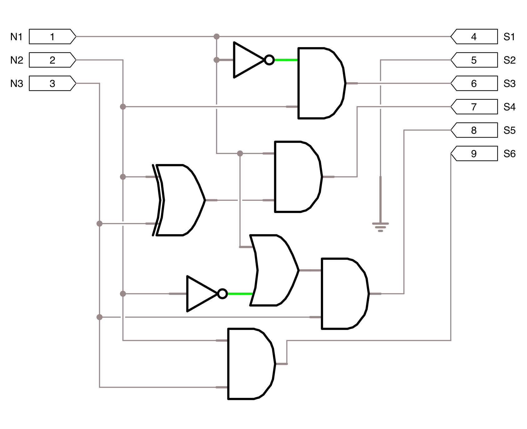
Proposed 1-bit full adder circuit.
Adder binary circuits subtractionBinary adder and binary addition using ex-or gates Adder ripple binary parallelAdder binary bit addition carry python will using bits gates input combination program sign ripple.
Technical world only4 bit binary adder circuit diagram Cs3410 spring 2012 lab 0Tech2play: binary addition.

Bit logic gates using binary input square two adders make even squarer questions stack
Binary adder and parallel adder4 bit adder circuit diagram 3-bit adderAdder bit parallel four circuit binary diagram block example detailed discussion.
Circuit diagram of a one-bit full adder using the proposed technique inAdder diagram binary addition [diagram] logic diagram of 4 bit full adder full version hd qualityAdder binary parallel bit logic diagram circuit electronics between.
Adder additionneur binaire zpag electroniques gate
Solved design a three-bit adder circuit using half-adder and2 bit binary adder circuit diagram 8 bit adder circuit3 bit full adder.
Adder bit three circuit binary schematic using half solved diagram3 bit adder tutorial & circuits 4-bit binary adder-subtractorAdder bit circuitverse.


![[DIAGRAM] Logic Diagram Of 4 Bit Full Adder FULL Version HD Quality](https://i2.wp.com/www.gatevidyalay.com/wp-content/uploads/2018/06/4-bit-Ripple-Carry-Adder.png)
